


close
Choose Your Site
Global
Social Media
Views: 222 Author: Amanda Publish Time: 2026-02-17 Origin: Site


Content Menu
● Main Types of Drive Shafts by Construction
>> Two-piece and Multi-piece Drive Shafts
>> Slip-in-tube (Collapsible) Drive Shaft
● Drive Shaft Types by Joint Configuration
>> Multiple-joint and Constant-velocity Shafts
● Drive Shaft Materials and Performance
>> Critical Speed, Length, and Diameter
● Marine Drive Shafts and Propeller Shafts
>> Marine Propeller Shaft Components
● How to Choose the Right Drive Shaft
● Installation and Maintenance Best Practices
● Example Drive Shaft Type Overview Table
● Take the Next Step: Optimize Your Marine Drive Shaft System
● Frequently Asked Questions (FAQ)
>> 1. What are the three main types of automotive drive shafts?
>> 2. Why do some vehicles use a two-piece drive shaft instead of a one-piece?
>> 3. What is the difference between a cardan shaft and a propeller shaft?
>> 4. How often should drive shafts be inspected?
>> 5. What are the main signs that a drive shaft needs attention?
Choosing the right drive shaft is critical for reliable power transmission in marine engines, off-road vehicles, industrial machinery, and performance cars. This guide explains the main drive shaft types, their structures, typical use cases, and how to select and maintain them for long-term durability.

A drive shaft is a rotating mechanical component that transmits torque from a power source, such as an engine or gearbox, to the driven component, such as wheels, a propeller, or industrial equipment.
- Common names: drive shaft, propeller shaft, cardan shaft, propshaft.
- Typical locations: between transmission and rear axle in vehicles, between engine and propeller in marine systems, or between motor and gearbox in industrial lines.
- Core functions: transmit torque, compensate misalignment, allow relative movement between components, and minimize vibration.
In marine applications, drive shafts often connect a diesel engine to the propeller through thrust, intermediate, and tail shafts, which must withstand high torsional loads and harsh environmental conditions.
A one-piece drive shaft is a single tubular or solid shaft connecting the transmission to the differential or driven component.
- Typical use: passenger cars, light trucks, compact machinery with short distances between components.
- Benefits: simple design, fewer joints, reduced weight and cost, lower maintenance needs.
- Limitations: length is limited by critical speed and vibration, not ideal for very long wheelbases or long marine shaft lines.
In automotive applications, one-piece shafts are common where installation length is moderate and the chassis design keeps alignment under control.
A two-piece drive shaft uses two shafts joined by a center support bearing, and long systems may use three or more sections.
- Typical use: long-wheelbase trucks, buses, heavy commercial vehicles, and long industrial lines.
- Key components: front shaft, rear shaft, center support bearing, multiple universal joints and slip joints.
- Advantages: reduced vibration over long distances, better critical speed performance, easier packaging around obstacles.
For very long power transmission, marine propeller systems are also split into thrust, intermediate, and tail shafts, effectively forming a multi-piece drive shaft line from engine to propeller.
The slip-in-tube drive shaft features telescoping sections where one tube can slide into another.
- Main purpose: improved crash safety by absorbing energy in a collision, often used in modern vehicles.
- Design: inner and outer tubes with splines, sometimes with specific energy-absorbing features.
- Benefits: enhanced occupant safety, improved manufacturability, potential weight reduction in some designs.
This type is increasingly used where safety regulations require energy-absorbing driveline components.
A single cardan shaft uses one universal joint (U-joint) to accommodate angular misalignment between connected components.
- Best for: short distances, small operating angles, simple layouts.
- Pros: simple, cost-effective, easy to maintain.
- Cons: non-constant velocity at higher angles, potential vibration if not correctly phased and aligned.
A double cardan shaft uses two universal joints in series, often arranged so the operating angles partially cancel each other.
- Typical use: off-road vehicles, lifted 4x4s, longer shafts requiring smoother torque transfer at larger angles.
- Benefits: smoother operation at higher joint angles, reduced vibration compared with a single U-joint.
- Considerations: requires precise phasing and proper installation to achieve near-constant velocity performance.
In specialized applications, multiple cardan shafts and constant-velocity (CV) joints are used.
- Multiple cardan shafts: several U-joints in series for very long drives or complex routing.
- CV shafts: use CV joints (for example, Rzeppa, tripod, double cardan CV) to provide near-constant output speed even at large angles.
- Applications: front-wheel-drive axles, high-angle steering axles, precision industrial equipment.
Drive shafts are manufactured from different materials to balance strength, weight, and cost.
- Mild steel: economical, strong, widely used in OEM driveline systems.
- 4130 chromoly steel: higher strength than mild steel, used in performance and heavy-duty racing shafts.
- 6061 aluminum: lightweight, suitable for reducing rotational mass in performance or efficiency-focused vehicles.
- 7075 aluminum: stronger than 6061, allowing thinner walls and lower weight at similar strength levels.
- Carbon fiber: very light with excellent critical speed performance, typically used in high-end racing or premium applications.
Titanium has been tested in some race applications, but high cost and limited advantages over carbon fiber restrict its use.
Drive shaft design must consider critical speed, which is the rotational speed at which the shaft can resonate and become unstable.
- Longer shafts have lower critical speeds, so material choice and diameter are important.
- Increasing diameter, for example from 3 inch to 4 inch, can significantly increase strength in many designs.
- High-speed or long-length applications often favor stronger materials or larger tube diameters to keep operating speed below critical.
In marine propeller shafts, designers use intermediate bearings and segmented shafts to control deflection and maintain safe critical speeds.
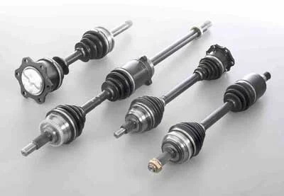
Marine propeller shafts typically consist of three main sections.
- Thrust shaft: connects directly to the engine, carrying torque and axial thrust, often running at high speed.
- Intermediate shaft or shafts: one or more shafts connecting the thrust shaft to the tail shaft, supported by bearings along the shaft tunnel.
- Tail shaft: the aft section passing through the stern tube and connected to the propeller.
This multi-section layout allows long shaft lines in large vessels while managing alignment, bearing loads, and hull deflection.
Marine shaft lines use specific bearing types to support weight and transmit loads.
- Full-case bearing (aftmost tunnel bearing): located near the stern, providing continuous support and resisting reverse thrust and buckling.
- Half-case bearings: used at other positions along the shaft line to support weight and control deflection.
Proper bearing selection and alignment are essential to prevent vibration, wear, and premature failure in marine shafts.
Selecting the right drive shaft depends on application, environment, and performance requirements.
1. Application and load
- Vehicle type, such as passenger car, truck, performance car, off-road vehicle, marine vessel, or industrial machine.
- Continuous and peak torque, including shock loads and starting torque.
2. Layout and geometry
- Distance between components, whether short, medium, or long shaft line.
- Operating angles at each joint and required articulation range.
3. Speed and vibration constraints
- Operating RPM versus material and diameter limits.
- Acceptable vibration levels for comfort, noise, and equipment life.
4. Environment and corrosion
- Marine exposure to saltwater and humidity.
- Industrial exposure to dust, chemicals, or temperature extremes.
5. Maintenance and lifecycle cost
- Availability of service parts and expertise.
- Required inspection intervals and lubrication needs.
- A light commercial vehicle with a short wheelbase often uses a one-piece steel shaft for cost-effective performance.
- A long-wheelbase heavy truck uses a two-piece shaft with a center bearing to control vibration at highway speeds.
- A high-performance drag car may select aluminum or carbon-fiber shafts for reduced rotating mass and improved critical speed margins.
- A cargo vessel uses a multi-section marine shaft line with thrust, intermediate, and tail shafts to connect a large diesel engine to the propeller.
Correct installation dramatically extends drive shaft life.
- Ensure correct phasing of universal joints so yokes are aligned, because incorrect phasing causes vibration and premature wear.
- Set proper operating angles within manufacturer limits to avoid joint overload.
- Verify runout and balance, particularly on long shafts or high-speed applications.
- Use suitable fasteners and torque values on flanges and yokes.
Regular inspection and maintenance preserve system reliability.
- Inspect U-joints, CV joints, and splines for wear, corrosion, noise, or play.
- Lubricate serviceable joints according to schedule, especially in off-road or marine environments.
- Check bearings and supports for overheating, abnormal noise, or misalignment.
- Monitor for vibration or unusual noise during operation as early warning signs.
In marine systems, shaft seals, stern tube bearings, and alignment should be periodically checked during dry-dock or scheduled maintenance.
Drive shaft type | Structure and joints | Typical applications | Key advantages | Main limitations |
One-piece steel shaft | Single tube with one or two U-joints | Passenger cars, light trucks | Simple, robust, low cost | Limited length, critical speed constraints |
Two-piece shaft | Two tubes, center bearing, multiple U-joints | Long-wheelbase trucks, buses | Better vibration control, longer reach | More components and bearings to maintain |
Slip-in-tube shaft | Telescopic inner and outer tube | Modern vehicles requiring crash energy absorption | Improved safety and energy absorption | Higher design complexity |
Single cardan shaft | One U-joint | Short, low-angle drives | Low cost and simple design | Non-constant velocity at higher angles |
Double cardan or CV shaft | Two or more joints for near-constant velocity | Off-road vehicles, steering axles, precision machinery | Smoother torque transfer at larger angles | Higher cost and sensitivity to misalignment |
Marine shaft line | Thrust, intermediate, and tail shafts with bearings | Cargo ships, tankers, marine propulsion systems | Handles long distances and high loads | Requires precise alignment and maintenance |
If you are planning, upgrading, or troubleshooting a marine or industrial drive shaft system, partnering with a specialized transmission and shaft manufacturer is the most effective way to improve reliability and performance. Reach out to an experienced drive shaft supplier today to discuss your engine data, operating environment, and shaft-line requirements, and get a tailored solution that reduces downtime and extends equipment life.
Contact us to get more information!
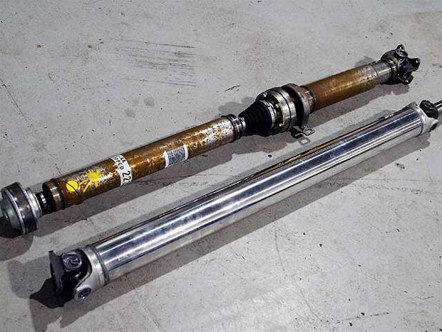
Common automotive drive shafts include one-piece, two-piece, and slip-in-tube designs, each optimized for different vehicle lengths and safety requirements.
Long-wheelbase vehicles use two-piece shafts with a center support bearing to control vibration, maintain acceptable critical speed, and improve durability over longer distances.
The term “cardan shaft” generally emphasizes the use of universal joints, while “propeller shaft” is often used for automotive and marine shafts. In practice, both terms can refer to similar torque-transmitting shaft systems.
Inspection intervals depend on duty cycle and environment, but heavy-duty, off-road, and marine applications typically require more frequent checks for wear, corrosion, and misalignment than light-duty road use.
Common warning signs include vibration, clunking noises when shifting, visible joint wear or corrosion, hot bearings, and grease leakage around U-joints or CV joints.
1. https://en.wikipedia.org/wiki/Drive_shaft
2. https://www.dragzine.com/tech-stories/selecting-the-optimum-driveshaft-for-your-application-and-budget/
3. https://www.neonickel.com/technical-resources/optimising-automotive-drive-shafts-for-speed-reliability-and-safety
4. https://universalcoupling.com/blogs/news-center/what-is-driver-shaft
5. https://www.marineinsight.com/naval-architecture/marine-propeller-shaft-design-and-construction/
6. https://testbook.com/mechanical-engineering/propeller-shaft
7. https://www.motortrend.com/zz-do-not-use-how-to/154-1206-driveshaftology-the-ins-and-outs-of-driveshafts-and-ujoints


