


close
Choose Your Site
Global
Social Media
Views: 236 Author: Gill Transmission Parts Publish Time: 2026-08-25 Origin: Site


Content Menu
● Corrosion Damage vs Mechanical Wear: The Core Difference
● What Corrosion Damage Looks Like
>> Crevice and Under-Deposit Corrosion
>> Galvanic and Stray-Current Corrosion
● What Mechanical Wear Looks Like
>> Adhesive Wear and Surface Smearing
>> Fretting Wear at Connections
>> Wear Caused by Misalignment
● How to Tell the Difference During Inspection
>> Inspection Methods That Add Value
● Root Causes: Why the Damage Started
>> Main Causes of Corrosion Damage
>> Main Causes of Mechanical Wear
● Repair Decisions: Restore, Sleeve, or Replace?
>> When Surface Restoration May Be Suitable
>> When Replacement Is the Better Choice
● Practical Prevention Plan for Vessel Operators
>> During Docking or Scheduled Maintenance
● Expert Perspective: Treat Surface Damage as a System Signal
● Choose a Reliable Marine Drive Shaft Partner
● FAQ
>> 1. What is the difference between corrosion damage and mechanical wear on a marine drive shaft?
>> 2. Can corrosion pits cause a marine drive shaft to fail?
>> 3. What causes shaft wear near the stern-tube bearing?
>> 4. How can I prevent corrosion on a marine propeller shaft?
>> 5. Can a scored marine drive shaft be repaired?
>> 6. Why does a repaired shaft keep developing the same damage?
>> 7. How often should a marine drive shaft be inspected?
Marine drive shafts work in an environment where saltwater, cyclic loads, vibration, heat, contaminants, and imperfect alignment can act at the same time. For vessel owners, repair yards, and marine equipment buyers, correctly distinguishing corrosion damage vs mechanical wear on marine drive shafts is essential: the visible mark may look similar, but the root cause, inspection method, repair decision, and prevention strategy are very different.
At Ningbo Gill Transmission Parts Co., LTD., our 29 years of experience in marine transmission components has reinforced one practical lesson: a shaft should never be evaluated by surface appearance alone. A polished groove may point to bearing-related mechanical wear; a cluster of pits may indicate electrochemical attack; and a crack near a corroded area can signal a more serious combined failure mechanism. The right diagnosis protects vessel availability, maintenance budgets, and propulsion-system reliability.

Corrosion damage is material loss caused by chemical or electrochemical reactions between the shaft surface and its environment. In marine service, seawater, oxygen, chlorides, stray current, damaged coatings, and failed seals are frequent contributors.
Mechanical wear is physical material loss caused by friction, abrasion, poor lubrication, misalignment, vibration, bearing overload, or debris between moving surfaces.
Although the two damage modes differ, they often occur together. For example, a damaged stern-tube seal may allow seawater to reach an unprotected shaft area. Corrosion starts first. Then the roughened surface accelerates seal-lip and bearing wear. If alignment is also poor, localized loading can turn a manageable defect into a costly shaft repair or replacement.
| Factor | Corrosion Damage on Marine Drive Shafts | Mechanical Wear on Marine Drive Shafts |
|---|---|---|
| Primary mechanism | Electrochemical or chemical attack | Friction, abrasion, loading, and surface contact |
| Typical appearance | Pitting, rust staining, crevice attack, under-film damage | Scoring, grooves, polishing, fretting, diameter reduction |
| Common locations | Seal areas, exposed shaft sections, joints, damaged protective zones | Bearing journals, seal tracks, coupling interfaces, spline or keyway areas |
| Major triggers | Seawater ingress, galvanic coupling, stray current, coating failure | Misalignment, inadequate lubrication, contaminated lubricant, debris, overload |
| Damage pattern | Often localized and irregular | Often follows the contact path or load zone |
| Hidden risk | Corrosion pits can become fatigue initiation points | Wear can increase clearance, heat, vibration, and misalignment |
| Main prevention | Material selection, sealing, electrical protection, coating integrity | Alignment control, lubrication, clearance monitoring, cleanliness |
Corrosion on a marine drive shaft is not limited to ordinary "rust." Different corrosion forms leave different signatures and require different corrective actions.
Pitting corrosion creates small but potentially deep cavities. It is especially dangerous because a shaft may retain a relatively smooth overall appearance while local pits reduce section strength and create stress concentrations.
On a propeller or drive shaft, pitting is commonly found near:
- Damaged shaft coatings or sleeves
- Seal contact zones
- Areas exposed after liner damage
- Water-lubricated bearing systems
- Crevices near fittings, couplings, or protective components
A shallow surface stain may be removable. A deep pit is different. It can become a focal point for crack initiation under repeated torsional and bending loads.
Crevice corrosion develops where seawater becomes trapped in narrow spaces with restricted oxygen flow. Typical locations include interfaces beneath liners, seal components, fasteners, and poorly protected shaft transitions.
This is why a shaft inspection should include more than an external visual check. Where accessible, inspectors should examine transitions between shaft, liner, seal track, and propeller connection. A hidden crevice can continue deteriorating long before the vessel crew sees an external symptom.
When dissimilar metals are electrically connected in seawater, one component can corrode faster than expected. This is known as galvanic corrosion. Stray-current corrosion can be even more aggressive when unintended electrical currents pass through the propulsion system.
Poor shaft grounding, damaged bonding arrangements, inadequate cathodic-protection control, and electrical faults may all contribute. A technical analysis published through AMPP's corrosion conference proceedings identified poor or absent shaft grounding as a potential explanation for severe propulsion-shaft corrosion associated with stray currents.
Corrosion fatigue is one of the most serious combined failure modes. It occurs when a shaft experiences cyclic stress while corrosion damages the surface. A pit or corrosion notch can serve as the starting point for fatigue cracking.
In practical terms, the sequence may be:
1. A seal problem allows water ingress
2. Localized corrosion begins
3. A pit forms in a highly stressed shaft zone
4. Repeated propulsion loads initiate a crack
5. The crack grows until repair, withdrawal, or failure becomes unavoidable
This is why "minor" corrosion should not be judged only by the visible area. Depth, location, shaft material, and loading history matter more than cosmetic appearance.
Mechanical wear is typically linked to contact, friction, movement, and load distribution. Unlike corrosion, it often creates a pattern that follows the path of a bearing, seal lip, coupling, or rotating contact surface.
Abrasive wear occurs when hard particles pass between the shaft and a mating component. Sand, silt, metallic particles, broken bearing material, and contaminated lubricant can all score a shaft surface.
Common indicators include:
- Long axial scratches
- Circumferential scoring
- Rough bearing journals
- Grooves in seal-running areas
- Embedded debris marks
- Uneven surface finish
For water-lubricated systems, sediment-heavy operating conditions can raise abrasive-wear risk. For oil-lubricated systems, contamination and lubricant degradation are key concerns.
Adhesive wear develops when two surfaces contact under excessive load or inadequate lubrication. Material may transfer from one surface to another, creating smearing, galling, or localized roughness.
This can occur when lubrication flow is insufficient, bearing clearance is incorrect, or the shaft line is operating outside intended alignment conditions. If left unresolved, friction can generate heat, damage bearing surfaces, and further degrade the shaft journal.
Fretting is caused by very small repeated movements between tightly fitted components. It may occur at couplings, flange faces, keyways, splines, shrink-fit areas, or propeller connections.
The damage often appears as:
- Dark oxide debris
- Red-brown or black staining
- Fine surface cracking
- Polished contact patches
- Localized wear around a fitted interface
Fretting is frequently mistaken for simple corrosion because oxidation products are present. The difference is that the oxidation is driven by micro-motion and contact pressure, not only by environmental exposure.
Misalignment is a major mechanical cause of marine drive shaft wear. When the engine, gearbox, intermediate shaft, bearing line, and propeller shaft do not share the correct operating geometry, loads become uneven.
The results may include:
- Uneven bearing wear
- Shaft journal scoring
- Higher vibration
- Elevated bearing temperature
- Seal leakage
- Coupling stress
- Reduced bearing life
DNV provides propulsion-shaft alignment services specifically focused on measurement verification, root-cause analysis, and improved shaft-line alignment. This reflects the industry reality that alignment is not a one-time installation task. Hull deflection, machinery movement, bearing settlement, temperature changes, and repairs can alter shaft-line behavior over time.
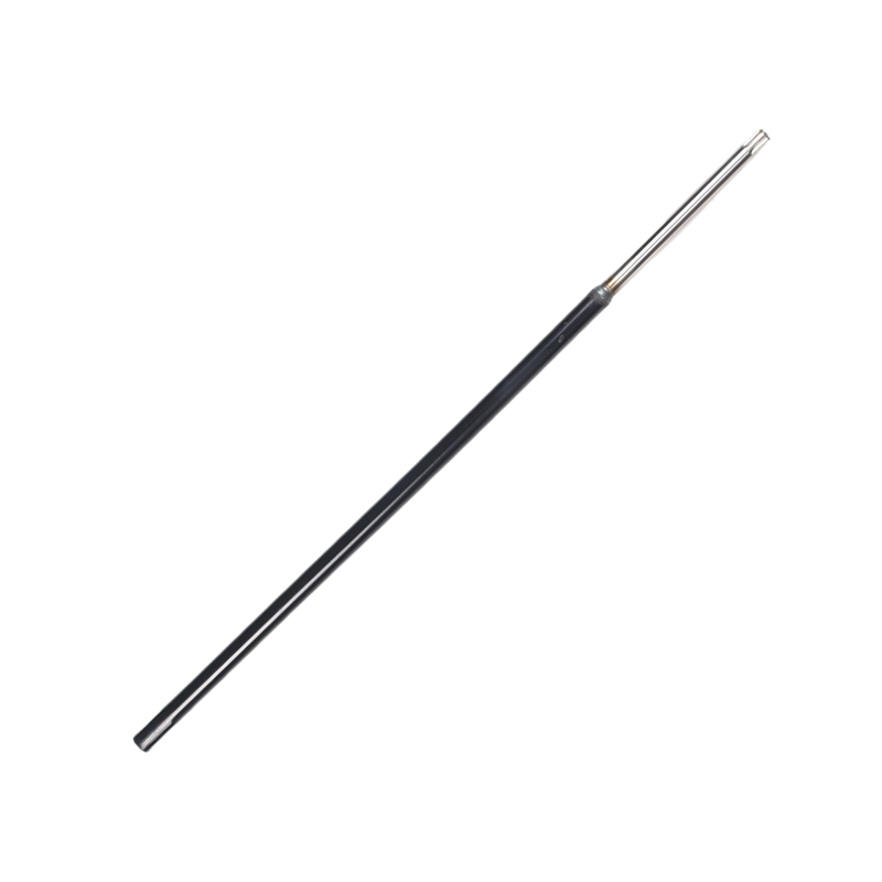
A reliable assessment combines visual evidence with measurements and operational history. Do not make a repair decision based only on a photograph or a single surface mark.
| Inspection Finding | More Likely Cause | What to Check Next |
|---|---|---|
| Random, deep, isolated pits | Corrosion damage | Pit depth, nearby coating failure, seal condition, electrical protection |
| Long grooves along the shaft axis | Abrasive mechanical wear | Bearing condition, debris source, lubricant cleanliness |
| Smooth polished band at a seal track | Normal contact or early mechanical wear | Seal pressure, shaft runout, surface finish, leakage history |
| Rust-like debris at a fitted connection | Fretting wear or corrosion | Interface movement, fit condition, torque, crack inspection |
| Uneven journal wear on one side | Misalignment or bearing-load issue | Shaft alignment, bearing clearance, vibration trend |
| Corrosion around an electrically connected area | Galvanic or stray-current corrosion | Grounding, bonding, anode condition, electrical isolation |
| Crack near a pit or keyway | Corrosion fatigue or stress-related damage | Non-destructive testing and engineering review |
A strong marine drive shaft inspection program usually includes:
- Visual inspection after cleaning the surface
- Dimensional measurement of shaft diameter and wear zones
- Shaft runout measurement to identify bending or distortion
- Bearing-clearance measurement and comparison with prior records
- Alignment verification during docking, overhaul, or after machinery work
- Lubricant or water-condition review where relevant
- Dye penetrant, magnetic particle, or ultrasonic examination when cracks or subsurface defects are suspected
- Vibration and temperature trend monitoring during operation
IACS-related shaft survey guidance calls for defined shaft survey methods, including examination of shafts, seals, and bearings, plus approved surface crack detection in critical propeller-connection areas for applicable configurations. It also emphasizes recording bearing clearances. These records are valuable because trend changes often reveal damage before a visible failure develops.
The visible damage is usually the final stage of a longer chain of events. Finding the root cause prevents repeated failure after repair.
- Seawater entering through worn or damaged seals
- Inadequate corrosion-resistant material selection
- Damaged shaft coating, sleeve, or liner
- Galvanic interaction between dissimilar metals
- Ineffective shaft grounding or stray electrical current
- Crevice conditions beneath fittings or protective parts
- Long periods of inactivity with trapped moisture
- Poor preservation during storage, transport, or installation
- Incorrect shaft alignment
- Bearing clearance outside design limits
- Lubrication failure or wrong lubricant
- Abrasive contamination from water, sediment, or debris
- Excessive vibration or propeller imbalance
- Seal misinstallation or incorrect seal loading
- Poor surface finish in a seal-running area
- Overload, shock load, or repeated rapid maneuvering
- Improper assembly tolerances at couplings or interfaces
A key point for vessel operators is that repairing the shaft without correcting the initiating condition is only a temporary solution. A new sleeve will not solve stray-current corrosion. A polished journal will not cure a misaligned shaft line. A replaced bearing will not last if contaminated lubricant remains in the system.
The correct repair route depends on defect type, depth, location, shaft material, design limits, class requirements, and the shaft's operating duty.
Controlled surface restoration may be considered when damage is shallow, localized, and outside critical strength zones. Depending on engineering approval, options can include:
- Precision polishing
- Grinding within allowable limits
- Machining and dimensional restoration
- Approved metal spray or coating systems
- Composite repair in suitable non-critical areas
- Shaft sleeve or liner renewal
- Seal-track restoration
The repair should restore not only dimensions but also surface finish, concentricity, hardness compatibility, and sealing performance.
Replacement is often the safer option when there are:
- Deep pits in highly stressed areas
- Cracks or suspected crack growth
- Significant diameter reduction
- Severe corrosion beneath a liner
- Repeated failure at the same location
- Distortion or excessive runout
- Damage near keyways, tapers, or coupling transitions
- Uncertainty about remaining fatigue life
A shaft is a load-bearing propulsion component, not merely a rotating bar. Decisions should be based on documented measurements and qualified engineering review, not visual judgment alone.
The most cost-effective maintenance strategy is to detect early change rather than wait for visible damage.
- Review shaft vibration, noise, and bearing-temperature trends
- Check lubricant level, condition, and signs of water contamination
- Inspect accessible seals for leakage or abnormal wear
- Note changes in propulsion response or stern-tube operating behavior
- Record any grounding, electrical, or cathodic-protection abnormalities
1. Clean the shaft surface before evaluation
2. Inspect seal tracks, sleeves, liners, and bearing-contact zones
3. Measure shaft diameter at repeatable reference points
4. Compare bearing-clearance readings with baseline data
5. Check shaft alignment after engine, gearbox, bearing, or hull work
6. Inspect propeller condition and balance-related damage
7. Perform non-destructive testing where pits, cracking, or high-stress defects are found
8. Review repair history to identify recurring locations or patterns
For seawater-lubricated stern-tube bearing arrangements, ClassNK notes that IACS requirements generally call for shaft drawing-out inspections at intervals of at least five years, while approved alternatives may be used where they provide an equivalent or higher level of safety. Actual survey scope and intervals should always follow the vessel's applicable class rules, flag requirements, shaft design, and condition-monitoring arrangement.
From a manufacturing and service perspective, the best question is not, "Can this mark be repaired?" It is, "What system condition created this mark?"
A marine drive shaft operates with seals, bearings, couplings, lubrication, electrical arrangements, hull geometry, and propeller loading. Corrosion damage indicates an environmental or electrical-control issue. Mechanical wear indicates a friction, alignment, lubrication, or load-distribution issue. When both are present, the investigation should begin with seal integrity, alignment history, bearing clearance, operating data, and electrical protection.
This system-level approach helps buyers and maintenance teams avoid three common mistakes:
- Treating corrosion as a cosmetic defect
- Assuming every groove is normal bearing wear
- Replacing parts without documenting dimensions and root cause
Whether you need a new marine drive shaft, a replacement shaft component, or technical support for a recurring shaft-damage issue, the right supplier should understand the relationship between material selection, precision machining, surface condition, fit-up accuracy, and operating environment.
Ningbo Gill Transmission Parts Co., LTD. brings 29 years of focused experience in the research, production, and supply of marine transmission components, including drive shafts. Share your shaft drawing, material requirements, vessel application, dimensional data, and damage photos with our team. We can help you evaluate manufacturing options and identify a practical path toward reliable long-term operation.
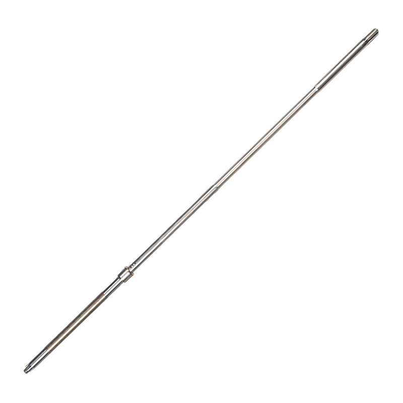
Corrosion damage is caused by environmental or electrochemical attack, while mechanical wear is caused by friction, abrasion, loading, movement, or lubrication problems. Corrosion commonly produces pits and irregular surface loss; mechanical wear more often produces grooves, scoring, or polished contact bands.
Yes. Deep or strategically located pits can act as stress concentrators. Under repeated bending and torsional loading, they may become starting points for fatigue cracks. Pit depth, location, shaft material, and operating load all affect the risk.
Common causes include bearing misalignment, incorrect clearance, abrasive contaminants, poor lubrication, inadequate water flow in water-lubricated systems, and shaft-line deflection. Inspection should include both the shaft journal and the full bearing and alignment condition.
Use suitable corrosion-resistant materials or protective systems, maintain shaft seals, prevent seawater intrusion, inspect coating and liner condition, manage galvanic compatibility, and verify shaft-grounding and electrical-protection arrangements. Regular inspection is essential because early-stage damage can be localized and difficult to see.
Some scored shafts can be restored through approved polishing, grinding, machining, coatings, or sleeve replacement. However, deep scoring, excessive diameter loss, cracks, or damage in highly stressed areas may require replacement. Measure the defect and assess it against engineering and vessel-class requirements before deciding.
Repeated damage usually means the root cause remains. Common unresolved causes include misalignment, contaminated lubrication, seal failure, incorrect bearing clearance, vibration, stray current, or poor component fit. The shaft repair should be combined with a system-level inspection.
Routine operational checks should be continuous or scheduled according to vessel service conditions. Detailed inspection frequency depends on shaft design, lubrication arrangement, class requirements, operating environment, and condition-monitoring results. Major surveys for many conventional arrangements follow defined multi-year class intervals, but vessel-specific requirements control.
2. [ClassNK — Alternative Inspection Methods for Seawater Lubricated Propeller Shafts]
3. [ClassNK — Propeller Shaft and Stern Tube Shaft Surveys]
4. [DNV — Propulsion Shaft Alignment Services]
5. [AMPP / CORROSION Conference — Analysis of Corrosion Damage on Propulsion Shafts]
6. [Taylor & Francis — Corrosive Wear of Bronze Propeller Shaft Sleeve]
7. [Hong Kong Marine Department — Propeller Shaft Survey Guidance Referencing IACS UR Z21]
8. [DNV-GL Guidance — Corrosion Protection and Shaft Alignment Requirements]


