


close
Choose Your Site
Global
Social Media
Views: 257 Author: Gill Transmission Parts Publish Time: 2026-11-11 Origin: Site


Content Menu
● What Does Boat Drive Shaft Alignment Actually Mean?
● When Should You Check Marine Propeller Shaft Alignment?
● Before You Begin: Safety, Tools, and Boat Condition
>> Perform Final Alignment Afloat
● How to Align Boat Drive Shaft Components: Step-by-Step
>> Step 1: Inspect the Mounts and Supporting Structure
>> Step 2: Separate and Clean the Coupling Faces
>> Step 3: Establish the Shaft's Correct Supported Position
>> Step 4: Measure at Four Clock Positions
>> Step 5: Compare Readings With the Correct Tolerance
>> Step 6: Adjust the Engine in Small Increments
>> Step 7: Rotate the Components and Recheck
>> Step 8: Tighten, Verify, and Commission
● Three Expert Checks That Prevent Misleading Results
>> 1. Separate Angular Error From Parallel Offset
>> 2. Do Not Transfer Flexible-Coupling Limits to Rigid Flanges
>> 3. Use Repeatability as a Quality Check
● Troubleshooting Boat Shaft Alignment Problems
● Choosing Marine Drive Shaft Components
>> Can I Align a Boat Drive Shaft Out of the Water?
>> What Is the Correct Boat Shaft Alignment Tolerance?
>> Should I Move the Shaft or the Engine?
>> Can a Flexible Coupling Fix Poor Alignment?
>> Does Vibration Always Indicate Shaft Misalignment?
>> Why Does the Gap Change When I Rotate the Shaft?
Learning how to align boat drive shaft components correctly starts with one principle: adjust the engine to the correctly positioned propeller shaft, rather than forcing the shaft to meet the engine. For conventional inboard installations, accurate alignment requires clean coupling faces, sound engine mounts, proper allowance for shaft sag, and measurements checked against the equipment manufacturer's specifications.
At Ningbo Gill Transmission Parts Co., LTD., our business focuses on the research, development, production, and sales of drive shafts and related marine components, backed by 29 years of professional experience. This guide combines that component-focused perspective with published marine engineering guidance to explain the inspection, measurement, and verification process.
The central rule is alignment before assembly force. Coupling bolts secure correctly positioned components; they should never pull a misaligned drivetrain into place.
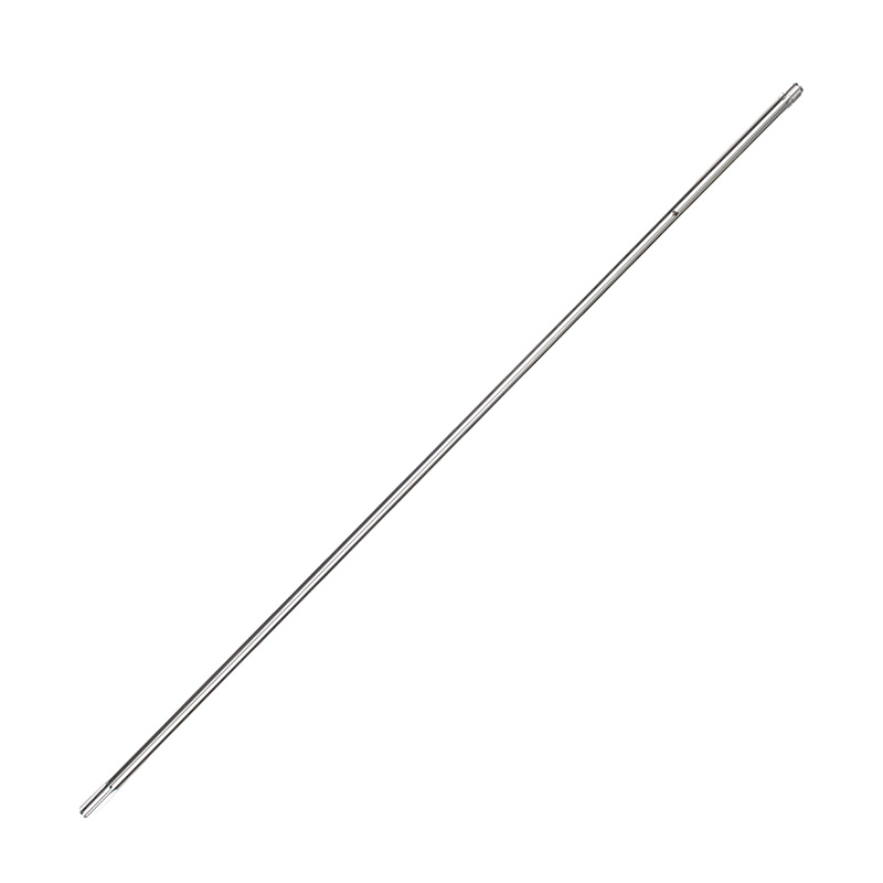
Two related tasks determine whether a conventional marine shaft installation operates correctly:
- Engine-to-shaft alignment positions the transmission output flange relative to the shaft coupling.
- Shaft-to-bearing alignment positions the shaft correctly through its supporting bearings.
A successful coupling check does not automatically prove that the bearings, strut, or shaft log are correctly positioned.
At the coupling, the objective is to achieve both concentricity and parallelism. Concentricity means the shaft and transmission output share the intended centerline. Parallelism means the mating flange faces do not form a wedge-shaped gap.
This article covers conventional inboard propulsion with a shaft coupling and adjustable engine mounts. Saildrives, sterndrives, and articulated driveline systems require their own procedures.
Check alignment after work that could change the relationship between the engine, shaft, and hull structure, including:
- Engine or transmission replacement.
- Engine mount replacement.
- Shaft, coupling, bearing, or strut repairs.
- Grounding or propeller impact.
- Significant structural repairs.
Difficult shaft rotation, uneven bearing wear, deteriorated mounts, or recurring coupling problems also justify investigation.
However, vibration alone does not establish misalignment. A damaged propeller, shaft runout, coupling eccentricity, or another rotating defect can produce vibration. An effective diagnosis separates these possibilities instead of treating mount adjustment as a universal cure.
Stop the engine, remove the starting key, and isolate starting power according to the vessel's procedures. Prevent accidental starting while anyone works near the coupling.
Never inspect or adjust an exposed rotating coupling with the engine running.
Before separating components, establish how the shaft will remain secured. Uncontrolled aft movement could disturb the shaft seal or create a more serious problem. Do not loosen shaft-retention hardware or seal components merely to gain measurement clearance.
Engine lifting, seized couplings, damaged mounts, and uncertain shaft support are reasons to involve a qualified marine technician.
Typical equipment includes:
| Tool or information | Purpose |
|---|---|
| Feeler gauges | Measure coupling-face gaps |
| Suitable spanners and sockets | Adjust mounts and coupling fasteners |
| Torque wrench | Tighten fasteners to specified values |
| Dial indicator and rigid fixture | Investigate runout or offset |
| Cleaning materials | Remove contamination from mating faces |
| Measurement worksheet | Record changes and repeatability |
| Equipment manuals | Confirm tolerances, torque, and procedures |
More complex installations may require optical or laser assessment of the shaft-bearing centerline.
An ashore check can establish preliminary alignment, but final engine-to-shaft alignment should take place afloat.
Hull shape can change between yard supports and normal buoyancy. Published marine guidance recommends allowing fiberglass and timber vessels at least 12 hours afloat before final checking; vessel-specific instructions may require longer.
Record fuel, water, and loading conditions so later measurements remain meaningfully comparable.
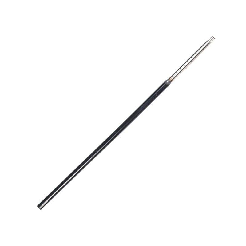
Inspect the engine mounts before measuring the coupling.
Look for cracked or separated rubber, corrosion, collapsed isolators, loose attachment hardware, and damaged adjustment threads. Check the supporting beds and brackets for movement or deterioration.
Adjusting an engine on defective mounts produces a temporary result at best. Replace or repair defective supporting components before alignment.
Also confirm that the mounts retain usable adjustment travel. Reaching the end of a stud's range can indicate an installation problem rather than a need for more adjustment.
Mark the original relationship between the coupling halves, then remove the coupling bolts according to the equipment procedure.
Separate the faces only as far as necessary. Avoid uncontrolled shaft movement.
Clean the mating surfaces and inspect for:
- Rust, paint, or embedded debris.
- Burrs around bolt holes.
- Damaged pilot registers.
- Cracks or distorted surfaces.
- Evidence of fretting or poor seating.
A contaminated face can create misleading readings. A damaged register can prevent proper centering even when the visible gap appears small.
The disconnected forward end of a shaft can sag under its own weight and the coupling's weight.
This matters because an engine aligned to a drooping shaft may load the shaft upward when the coupling bolts are tightened.
A marine alignment specialist can establish the intended shaft centerline using appropriate support calculations or optical methods. Do not lift the coupling by an arbitrary amount until the faces appear to match.
For long shafts, multiple bearings, or suspected strut displacement, investigate shaft-to-bearing alignment before adjusting the engine.
With shaft support addressed, bring the coupling faces together without using the bolts to close a gap. Engage the centering register as the coupling design requires.
Measure with feeler gauges at:
1. 12 o'clock.
2. 3 o'clock.
3. 6 o'clock.
4. 9 o'clock.
Record the readings before changing anything.
A larger top-to-bottom difference suggests angular error in the vertical plane. A side-to-side difference suggests angular error horizontally.
However, face measurements alone do not fully establish concentricity. Depending on coupling design, centering requires correct register engagement and possibly dial-indicator measurements.
Use the engine, transmission, and coupling manufacturers' specifications—not a number copied from another boat.
As a general reference, published marine guidance describes approximately 0.001 inch of face misalignment per inch of coupling diameter, capped at 0.004 inch. It also identifies transmission applications with a stricter 0.003-inch overall limit.
These are reference values, not universal acceptance criteria.
For example, a four-inch coupling should not automatically be accepted at 0.004 inch when its transmission documentation specifies 0.003 inch.
Flexible couplings can use entirely different measurement locations and limits.
Adjust the engine mounts to bring the transmission flange into the correct relationship with the shaft coupling.
Vertical adjustment changes height and pitch. Lateral movement changes side-to-side position and horizontal angle.
Work systematically:
- Record the starting readings.
- Make one controlled adjustment.
- Recheck all four positions.
- Note whether the change improved or worsened alignment.
- Repeat until measurements satisfy the specified procedure.
Mounts act as pivot points, so raising one part of the engine can move the output flange differently from what intuition suggests.
Avoid forcing the shaft sideways, using the seal as a support, or tightening coupling bolts to conceal an unresolved gap.
Rotate the shaft coupling 180 degrees and repeat the measurements. Where the equipment procedure permits, check the transmission flange separately as well.
This helps distinguish installation misalignment from an inaccurate rotating component.
If the largest gap moves with the shaft coupling, suspect coupling-face error, shaft runout, or an incorrect coupling-to-shaft fit. If the gap remains in the same physical location, engine positioning may remain the dominant issue.
Treat this as diagnostic evidence, not a complete diagnosis. A shaft shop may need to inspect the assembly and perform fitting and facing.
Secure the mount adjustments using the specified method. Hold adjustment nuts as necessary so tightening the locknuts does not change the setting.
Recheck alignment afterward.
Install the coupling fasteners and tighten progressively in the specified sequence to the correct torque. Confirm required locking arrangements.
Finally:
- Verify that guards are reinstated.
- Check the shaft seal installation.
- Confirm permitted manual rotation.
- Conduct a controlled operational test.
- Inspect for leakage and abnormal operation.
Any running assessment must take place with personnel clear of rotating machinery.
A nearly even coupling-face gap does not necessarily prove that both rotational centerlines coincide.
Angular error concerns the relative angle between the faces. Parallel offset concerns displaced centerlines.
This distinction explains why a feeler gauge is useful but not sufficient for every installation. Coupling-register condition and the appropriate offset measurement method remain important.
For its R&D flexible coupling, PYI describes checking the same red cone-headed bolt at four rotational positions, with a recommended maximum-to-minimum gap difference of 0.010 inch, or 0.25 mm.
That measurement belongs to that coupling's specified inspection method.
It does not mean a conventional rigid flange joint can accept a 0.010-inch face gap. Always match the tolerance to the exact component and measurement location.
Consider an illustrative case: flange measurements improve after adjustment but change again when the mount locknuts are tightened.
The useful conclusion is not simply "adjust it again." First determine whether tightening moved the engine, a mount is unstable, or the measurement setup changed.
Repeatability provides evidence that the result is mechanically stable.
For maintenance teams, a useful alignment record includes vessel loading, coupling identification, shaft-support method, clock-position readings, rotational checks, and final fastening details.
| Observation | Possible explanation | Appropriate response |
|---|---|---|
| Readings change after locking mounts | Adjustment shifted or support is unstable | Inspect mounts and repeat the locking procedure |
| Largest gap follows coupling rotation | Face error, runout, or poor fit | Investigate with suitable measuring equipment |
| Shaft remains difficult to rotate | Bearing, seal, shaft, or alignment issue | Assess the complete shaft line |
| Engine reaches adjustment limits | Installation geometry or mount problem | Review beds, brackets, and component selection |
| Alignment changes after launching | Hull support conditions changed | Complete final checks afloat |
Do not replace investigation with repeated adjustment. A correctly manufactured shaft cannot compensate for misplaced bearings, and careful engine positioning cannot straighten a bent shaft.
For replacement or new-build projects, provide the supplier with shaft dimensions, coupling details, transmission identification, bearing arrangement, and relevant drawings.
Discuss the required material, fit, straightness, and inspection criteria before production. Dimensional compatibility alone does not establish suitability for the complete propulsion system.
Ningbo Gill Transmission Parts Co., LTD. welcomes inquiries for marine drive shafts and related components. Send your drawings, existing-part measurements, application details, and inspection requirements so our team can review the component specification before quotation.

You can perform preliminary checks ashore. Complete final engine-to-shaft alignment afloat after the hull has settled, following the vessel's instructions.
There is no universal tolerance. Use the applicable equipment specifications and distinguish rigid-flange face measurements from flexible-coupling checks.
For routine engine-to-shaft alignment, adjust the engine to the correctly established shaft position. A displaced bearing or strut requires a separate assessment.
It can accommodate specified movement or limited misalignment. It does not replace correct installation or repair damaged mounts, bent shafts, or misplaced bearings.
No. Propeller damage, rotating-component runout, and other drivetrain problems can cause vibration. Diagnose the source before adjusting the engine.
The coupling face, shaft, or their fit may not run true. Investigate the rotating assembly rather than assuming further mount adjustment will solve the problem.
1. Steve D'Antonio Marine Consulting. "Engine Alignment." August 21, 2025. Detailed guidance on shaft sag, afloat checks, coupling measurements, rotational verification, and engine adjustment. [stevedmarineconsulting]
2. Steve D'Antonio Marine Consulting. "The Ins and Outs of Engine and Shaft Alignment Part I." August 25, 2016. Guidance on mount inspection, flange preparation, reference tolerances, and coupling assembly. [stevedmarineconsulting]
3. Steve D'Antonio Marine Consulting. "The Ins and Outs of Shaft Alignment Part II." September 26, 2016. Explanation of shaft-bearing geometry, installation accuracy, and engine adjustment limits. [stevedmarineconsulting]
4. PYI Inc. "Flexible Shaft Couplings." Manufacturer instructions covering R&D coupling installation, red-bolt alignment checks, and operating-temperature torque verification. [pyiinc]
5. Steve D'Antonio Marine Consulting. "Shaft Couplings." Technical discussion of coupling fit, facing, and runout inspection. [stevedmarineconsulting]
6. Steve D'Antonio Marine Consulting. "July 2025 Newsletter – Risers and Siphon-Breaks." Discussion distinguishing alignment problems from vibration associated with rotating-component irregularities. [stevedmarineconsulting]


