


close
Choose Your Site
Global
Social Media
Views: 268 Author: Gill Transmission Parts Publish Time: 2026-11-08 Origin: Site


Content Menu
● What Are the 3 Parts of an Outboard Motor and Their Functions?
● 1. The Outboard Powerhead: Where Mechanical Power Begins
>> What the Powerhead Does Not Do
● 2. The Outboard Midsection: More Than a Connecting Housing
>> Driveshaft Housing and Power Transfer
>> Cooling-Water and Exhaust Pathways
>> Mounting, Steering, and Tilt
● 3. The Outboard Lower Unit: Where Rotation Becomes Propulsion
>> How Outboard Gears Transfer Power
>> How Forward, Neutral, and Reverse Work
>> Bearings, Seals, and Lubricant Matter Together
● How the Three Outboard Motor Sections Work Together
● A Practical Inspection Framework: Follow the Symptom, Not the Assumption
● The Fishing-Line Failure Chain: A Small Problem With Wider Consequences
● What Marine-Parts Buyers Should Check Before Ordering Outboard Gears
>> Establish Exact Compatibility
>> Evaluate the Gear as an Engineered Component
● Maintain Each Section According to Its Function
● Turn Better Component Knowledge Into Better Purchasing Decisions
>> What Are the 3 Main Parts of an Outboard Motor?
>> Is the Powerhead the Same as the Cowling?
>> Where Are the Gears Located in an Outboard Motor?
>> What Is the Difference Between a Driveshaft and a Propeller Shaft?
>> Does Milky Lower-Unit Oil Always Mean a Damaged Propeller-Shaft Seal?
>> Can Outboard Gears Be Selected by Horsepower Alone?
What are the 3 parts of an outboard motor? The three main sections are the powerhead, the midsection, and the lower unit. The powerhead generates mechanical power, the midsection connects and supports the assembly, and the lower unit transfers rotation to the propeller.
Understanding these sections helps boat owners describe problems accurately, technicians organize inspections, and marine-parts buyers identify suitable replacement components.
At Ningbo Gill Transmission Parts Co., LTD., our focus is on the components that keep this power moving: outboard gears, drive shafts, propeller shafts, and related marine transmission parts. With 29 years of industry experience, we approach outboard anatomy from a practical perspective—understanding each section matters, but understanding how they interact matters even more.
This guide explains conventional gasoline-powered outboards. Electric outboards and specialized transmission designs may use different arrangements.
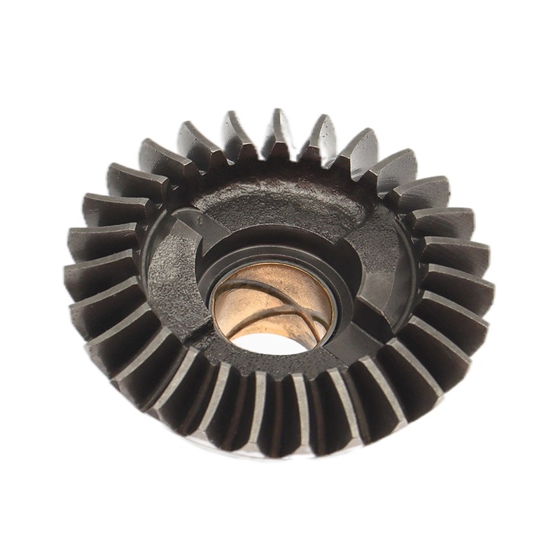
An outboard combines an engine, supporting structure, transmission, and propeller into one externally mounted propulsion system.
| Main section | Typical location | Primary function | Key components |
|---|---|---|---|
| Powerhead | Top, beneath the cowling | Converts fuel energy into rotating mechanical power | Cylinders, pistons, connecting rods, crankshaft, ignition and fuel systems |
| Midsection | Between powerhead and lower unit | Supports the assembly and provides pathways for power, cooling water, and exhaust | Driveshaft housing, driveshaft, water tube, exhaust passages |
| Lower unit | Bottom, normally submerged during operation | Changes the direction of power transmission and drives the propeller | Gearcase, gears, clutch mechanism, propeller shaft, bearings, seals |
These are functional sections, not three individual replacement parts. Each contains multiple components with different inspection and maintenance requirements.
The powerhead is the engine assembly at the top of the outboard. Its removable outer cover, called the cowling, protects the machinery beneath it.
Combustion creates pressure inside the cylinders. That pressure moves the pistons, which connect to the crankshaft through connecting rods.
The crankshaft converts this reciprocating motion into rotation. That rotation then passes into the vertical driveshaft.
Important powerhead components include:
- Engine block and cylinders.
- Pistons and connecting rods.
- Crankshaft and bearings.
- Cylinder head assemblies.
- Fuel-delivery and ignition systems.
- Cooling passages and lubrication components.
The exact arrangement depends on the engine. A four-stroke powerhead typically has a valve train and separate crankcase lubrication. Two-stroke designs use different gas-exchange and lubrication arrangements.
The powerhead does not directly turn its crankshaft into propeller thrust.
It produces rotating mechanical power. The driveshaft and lower-unit transmission carry that power to the propeller, which interacts with the water to produce thrust.
This distinction helps prevent a common diagnostic mistake: assuming every loss of boat speed is an engine problem. The cause may instead involve the propeller, gearcase, installation, or operating conditions.
The midsection sits between the powerhead and lower unit. Although it looks relatively simple from outside, it performs several important structural and routing functions.
The vertical driveshaft passes through the midsection, transferring rotation from the crankshaft to the lower-unit gearing.
The housing supports the overall assembly while keeping the shaft and associated passages properly located.
For replacement-parts buyers, shaft length and spline configuration are essential identification details. Matching horsepower alone does not establish compatibility.
On a typical water-cooled outboard, cooling water travels upward from the lower-unit area to the powerhead through a water tube.
Exhaust travels downward through passages in the assembly. Many conventional outboards discharge much of their exhaust through the propeller hub, although routing varies by model.
Consequently, a cooling problem can cross section boundaries. An overheating powerhead may have a problem originating at a water intake, pump, water tube, or internal cooling passage.
The mounting and swivel-bracket assembly connects the outboard to the boat's transom and supports steering and tilt movement.
Depending on the model, lifting and trimming may be manual or powered.
The practical lesson is simple: the midsection is not an empty spacer. Its structural condition and associated mounting hardware deserve attention alongside the engine and gearbox.
The lower unit contains the transmission components that deliver power to the propeller shaft. Its exterior commonly includes the gearcase, water intakes, anti-ventilation plate, and skeg, with the propeller mounted on the shaft.
This section operates in a demanding environment: underwater, under load, and exposed to impact risks and contamination.
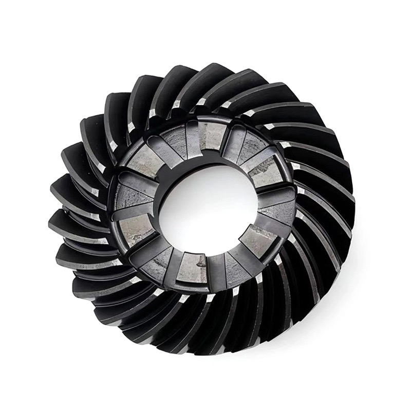
In a conventional mechanical-shift gearcase, a pinion gear driven by the vertical driveshaft meshes with forward and reverse gears.
The gear arrangement redirects rotation approximately 90 degrees to the horizontal propeller-shaft axis. It also provides the specified reduction ratio between engine and propeller speeds.
The three familiar gear names are:
1. Pinion gear.
2. Forward gear.
3. Reverse gear.
These are three transmission components inside the lower unit—not the three main sections of the complete outboard motor.
Many conventional outboards use a sliding clutch dog to connect the propeller shaft to either the forward or reverse gear.
In neutral, neither gear is locked to drive the propeller shaft. The engine can therefore continue running without intentionally driving the propeller.
Transmission arrangements vary. Some small engines and specialized models do not use this exact configuration, so the model-specific service manual remains the controlling reference.
Gears depend on more than tooth strength.
Bearings maintain support and alignment. Seals retain lubricant and help exclude water. Correct assembly settings establish the required operating relationships between components.
From a manufacturing perspective, a replacement gear should therefore be evaluated as part of a transmission system—not as an isolated metal part.
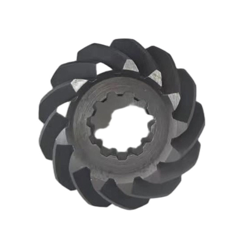
The power pathway is straightforward:
1. Combustion moves the pistons.
2. Connecting rods turn the crankshaft.
3. The crankshaft drives the vertical driveshaft.
4. Lower-unit gears redirect rotation and provide reduction.
5. The selected gear drives the propeller shaft.
6. The propeller produces thrust in the water.
Cooling follows a connected but different pathway: water enters through the intake system and is circulated toward the powerhead.
This interaction explains why physical location alone cannot establish a fault. Symptoms appear where the system reacts, not necessarily where the original problem begins.
Before inspection, stop the engine, remove the key, disconnect the emergency-stop lanyard, and follow the manufacturer's isolation procedure. Keep hands clear of the propeller whenever accidental starting is possible.
The following framework helps organize observations; it does not replace professional diagnosis.
| Observation | Areas worth investigating | Appropriate next step |
|---|---|---|
| Engine starts poorly or runs unevenly | Fuel, ignition, compression, electrical supply | Follow the model-specific engine troubleshooting procedure |
| Engine revs increase but boat speed does not respond normally | Propeller, hub, ventilation, loading, drivetrain | Reduce load and investigate before continued operation |
| Shifting becomes difficult or engagement is unreliable | Controls, linkage, adjustment, internal clutch components | Avoid forcing engagement; arrange inspection |
| Gear lubricant appears milky | Possible water intrusion | Have the gearcase checked for leakage |
| Large metal chips appear in drained lubricant | Possible internal damage | Obtain professional inspection before further use |
Fine metallic residue and large fragments should not be treated as equivalent findings. Manufacturer guidance distinguishes normal fine wear material from larger debris that requires investigation.
One useful maintenance lesson begins outside the gearcase.
Fishing line can wrap around the propeller shaft behind the propeller. If it damages a shaft seal, water can enter the gearcase and contaminate the lubricant.
The potential sequence is:
1. Line accumulates behind the propeller.
2. The seal becomes damaged.
3. Water enters the lubricant.
4. Lubrication and corrosion protection are compromised.
5. Internal components face increased damage risk.
This is why propeller removal and shaft inspection matter even when the engine seems healthy.
Milky lubricant warrants investigation, but appearance needs interpretation: recently agitated oil can contain fine air bubbles. Follow the manufacturer's checking procedure rather than diagnosing seal failure from color alone.
For distributors and repair businesses, understanding outboard anatomy should lead to better purchasing decisions.
A listing that says "fits a 15 HP outboard" is not enough to approve a critical transmission component.
Prepare the following information:
- Engine brand, model designation, and serial number.
- Original part number and any superseded numbers.
- Production-year or serial-range applicability.
- Gearcase version and rotation configuration.
- Relevant shaft, spline, and gear dimensions.
- Required quantity and intended application.
Where identification remains uncertain, drawings, dimensional inspection, or an original sample may be necessary.
A practical supplier review should address tooth geometry, bore dimensions, mating features, material specification, heat treatment, and inspection requirements.
Where applicable, discuss surface hardness and hardened-layer depth rather than accepting "high hardness" as a complete quality statement.
Do not invent universal acceptance values. Suitable tolerances and assembly settings depend on the specific design.
At Ningbo Gill, our manufacturing focus includes outboard gears and shafts. Our recommendation is to establish the technical specification before comparing quotations. A lower unit price offers little value if compatibility remains unresolved.
A useful maintenance plan separates tasks while recognizing their connections.
- Powerhead: follow engine-specific fuel, ignition, lubrication, and cooling requirements.
- Midsection: inspect accessible structure, mounting hardware, and associated pathways according to the manual.
- Lower unit: inspect external damage, propeller condition, shaft contamination, seals, and lubricant.
Use the specified marine gear lubricant and replacement sealing components. Do not assume automotive gear oil is suitable.
Service intervals are model-dependent. For example, Yamaha's general lower-unit guidance specifies an initial lubricant change after 20 hours, followed by 100-hour intervals. Always verify the instructions for the exact engine and operating conditions.
Flush after saltwater or dirty-water use using the approved procedure. Some flushing methods require the engine off; never assume every connection permits running.
Knowing the three main outboard sections makes conversations between owners, technicians, and suppliers more precise.
For marine-parts importers, distributors, and repair businesses sourcing replacement gears or shafts, send Ningbo Gill Transmission Parts Co., LTD. your engine identification, original part numbers, drawings or samples, and quantity requirements.
Our team can review the application and discuss suitable manufacturing or supply options. Start with verified specifications—not visual similarity.
They are the powerhead, midsection, and lower unit. These sections generate power, connect and support the assembly, and transmit rotation to the propeller.
No. The powerhead is the engine assembly. The cowling is the protective cover fitted around it.
The main propulsion gears are inside the lower-unit gearcase. Conventional mechanical-shift arrangements commonly include pinion, forward, and reverse gears.
The driveshaft typically runs vertically from the powerhead toward the gearcase. The propeller shaft runs horizontally from the gearcase to the propeller.
No. Milky lubricant can indicate water contamination, but the leak location requires testing. Recently agitated oil can also contain bubbles that complicate visual assessment.
No. Confirm the model, serial range, part number, gearcase configuration, and relevant dimensions. Similar horsepower ratings do not guarantee interchangeable transmission parts.
1. Universal Technical Institute — "What Is an Outboard Motor & How Does It Work?" Educational overview supporting the three-section classification and component functions. [uti]
2. Sport Fishing — "Outboard Motor Maintenance, How It Works." Technical explanation of the cowling, powerhead, vertical driveshaft, lower unit, and water-pump location. [sportfishingmag]
3. Yamaha Outboards — "Lower Unit Maintenance." Manufacturer guidance on lubrication, fishing-line damage, water contamination, metallic debris, sealing washers, and lubricant-change intervals. [yamahaoutboards]
4. Yamaha Outboards — "Freshwater Flushing Adds Years to the Life of an Outboard." Manufacturer guidance on salt and contaminant removal and flushing methods. [yamahaoutboards]
5. Mercury Marine — "Quick Tip: How to Remove Fishing Line from Your Prop Shaft." Manufacturer explanation of fishing-line damage to gearcase seals. [mercurymarine]
6. Ningbo Gill Transmission Parts Co., LTD. — "About Us." Company-reported background, establishment in 1997, product specialization, and manufacturing capabilities. [gilltransmission]


